Tuesday, November 15, 2016

MetroCluster Notes

 Why MetroCluster:


To run business critical applications which needs zero Recovery Point Objective (RPO) and minimal RECOVERY TIME OBJECTIVE (RTO) and also to withstand multiple components failure events ( Hardware failure, power outage and Natural disaster )

è Zero Data Loss

è Set it once simplicity

è Automatic Replication

è Seamless integration

è Supports both SAN & NAS

è Ability to perform Maintenance

è Ability to perform tech refresh

è Metro Cluster enables the maintenance beyond DC


Types of MetroCluster

Stretched MetroCluster: - Where the DR site can be of not more than 500meters (No switches or bridges are required by default as the connection will be direct using optical cable)


Two-node setup without ATTO bridges and only with optical cable

è Bridges or switches not required

è Supports optical connectivity

è Virtual interface over Fibre Channel (FC-VI) is cabled directly

è Connections are direct across sites using patch panels to disk shelves with optical SAS

Two-node setup with SAS bridges

è ATTO bridges are required  ( Refer ATTO Bridge to know more )

è FC-VI is cabled directly

è Maximum distance is 500m with 2Gbps or 150m with 8Gbps 


Fabric-attached MetroCluster: - Which can be extended up to 200Kms


Some Key Points to note:

The root aggregate requires two or three disks

Need to have minimum of two shelves per site

Disk assignment must be manual even in the event of disk failure as well

ISL and redundant fabrics connect the two clusters and their storage

All Storage is fabric attached and visible to all nodes


Now we need to understand how data is secured attaining zero downtime with MetroCluster

èMetro cluster uses Syncmirror technology to perform continuous data synchronisation across the DR site with aggregate mirroring

è Writes are mirrored synchronously to both plexes and by default Read operation happens
From local plex

è A special hidden volume that contains metadata is located in the data aggregate of each
Node or in a single aggregate in a cluster holds all the meta data.


Note:- All Aggregates are mirrored with the copies at DR site including root aggregate

To dig in more: How the whole site data replicated to DR

In aggregate mirroring, a mirrored aggregate is one WAFL ( Write Anywhere File Layout ) storage file system with two physically separated and synchronously updated copies on disks or array LUNs. The copies are called Plexes.

Data ontap always names the first plex as plex0 and second plex1. Each flex is a physical copy of the same WAFL file system and consists of one or more RAID groups.

As we know syncmirror can be used only at aggregate level ( Including all flexvol in the aggregate ) but not flexvol, each aggregate will have two synchronously mirrored plexes, the local plex, plex0 and the remote plex, plex1. Data is written to the local plex, plex0 and then synchronously replicated to remote plex, plex1 over the ISL. Reads are always from the plex0.

 As we see above Securing data is ok but how about configuration is secured

Here comes the NVRAM in to picture, NVRAM on each node is split in to four partitions to make the full use of NVRAM memory.

Note:- Each Node mirror its NVRAM to two other node: its HA partner and its DR partner

In normal operation, three of the four NVRAM partitions are used

Partition 1:  For the node self

Partition 2: For HA partner

Partition 3: For DR partner

And partition 4 would manage additional node in the event of takeover and switchover.

The overhead of the NVRAM split is managed by System Performance Modeler (SPM) tool,  which is not affected when compared to 7-Mode

Configuration replication service (CRS) replicates the configuration of each cluster to another.
By default a volume of 10GB size is created on each node to hold the replicated cluster data. Which acts as meta data volume.

Ex:- A change on Cluster A is logged in to the cluster A metadata volume and then CRS replicates the change to cluster B

MetroCluster Replication Mechanism

è NVRAM is mirrored to the HA partner and to the DR partner

è Disk traffic is mirrored at the aggregate level

è Cluster configuration is replicated over a peered network, Which means this doesn’t need a dedicated network

Reviewing the Failure Events:

Failure Events
7-Mode
2-Node DR group
4-Node DR group
One disk or two disk Failure
Data is still available
More than two disk failure
The serving plex serves data; the node is unaffected
Shelf failure
The surviving plex serves data
Switch failure
Data is served via the other path
Switch ISL failure
Data is available from the local node if the ISLs are down, DR protection is offline
Node Failure ( Panic, Power-off, and so on)
Automatic failover occurs to the remote node
Peered clusted link failure
n/a
Data remains available from the local cluster, cluster config changes are not replicated affecting DR
Failure of both nodes in an HA group
All data offline
All data offline
Automatic switchover (SO) with tie-breaker occurs


How a failure is detected ? What would be the plan of action after a failure of site ?

When there is complete site failure the surviving storage controller cannot distinguish between site failure or just a network partition. Here come the tie breaker in to picture which needs to be deployed in a separate data center which helps the surviving controller to decide what to do next.

Note: If the third data center is not available and Tie-Breaker cannot be implemented the storage controller takes no action and the storage administrator needs to do manual forced takeover of the storage resources on the surviving controller. ( Imagine you have only a production and DR site and don't have a third site), scratching your head where to deploy TIE-BREAKER setup a server in your office and install REDHAT (Tie breaker runs on Redhat Linux ) which will monitor your both sites or data center and instruct your MetroCluster what to do in the event of a failure.


Here are the mediums to monitor MetroCluster

Tie Breaker: After installing tie breaker on Redhat Linux, use the command

netapp-metrocluster-tiebreaker-software-cli  to use the metrocluster monitoring commands

Check the status of the MetroCluster

monitor show -status (Look for Intersite Connectivity, Reachable status)


monitor show -stats ( Shows when was the last cluster unreachable time, last intersite connectivity down time )


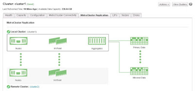
Another way to monitor the MetroCluster is from OCUM (Oncommand Unified Manager)

MetroCluster connectivity showing all healthy


MetroCluster Replication Status


In case of any failure, status changed as below


Also we can check the status of MetroCluster from the Ontap console:

metrocluster show


Recommended or Supported FAS controllers, Disk shelves and FC switch:

Controllers( Including Flex Arrays)
Disk Shelves
Switches
FAS 3220, 3250

FAS 6210, 6240, 6280, 6220, 6250, 6290

FAS 8020, 8040, 8060, 8080 EX

DS 4243

DS 2246

DS 4246
Brocade 6505

Brocade 6510

Cisco 9148


 Although zero downtime is assured there are very few demerits in MetroCluster and the beauty of NetApp is they actually admit these

è Switchover is disruptive for SMB protocol, where continuous available shares will have less than 60Seconds outage 

  è Doesn’t support infinite volume 

è SSD partitioning in Flash Pool

è Advance Disk Partitioning (ADP)

è NetApp Storage Encryption (NSE) 


Thursday, November 10, 2016

NetApp Snapshot directories appears to have wrong date


There might be mismatch of time stamp for snapshot at the NetApp controller end versus the time displayed in the windows explorer date modified.

Example:- The snaplist of my filerserver volume snapshots showing different time stamps 

Controller 


Windows Explorer


As we see comparing the screenshots above that there is difference between the snapshot time and the time in the explorer i.e., date modified 

Actually we shouldn't compare the snapshot time stamp against the Data Modified but we should look for the option Date Accessed which is same as the snapshot time stamp

Right click on the any of the tab above ( Ex:- Name, Date Modified, Type, Size ) and select more 


Now look for the option Data Accessed and select and ok


Now compare the time stamp from snapshot and the date access, will exactly the same 


Tuesday, October 18, 2016

Adding in a new disk shelf on Netbackup Appliance


1.     Rack mount the New disk shelf (xx TB)

Whenever i have added a disk shelf i have taken the whole system down first as we are plugging in SAS cables here - so i like to work on the safe side and this also ensure the bus is fully scanned too.

2. Connect the SAS cables from new Disk shelf (2*SAS IN) to the existing Appliance disk shelf (2* SAS out ports)


3. Power ON New disk shelf and wait for 10-20 mins to let initialize the disk shelf completely.

     
Depending on your configuration (Master/Media) (Advanced Disk Pool / Dedupe Pool) you'll have the following partitions (volumes) available.

Advanced Disk
Configuration
MSDP

Once you add the new tray you'll get an extra disk (highlighted below)
You can then decide which partitions to increase.
- [Info] Performing sanity check on disks and partitions... (5 mins approx)
----------------------------------------------------------------------------------
Disk ID     | Type                   | Total             | Unallocated | Status
----------------------------------------------------------------------------------
5E000000000000000000000000 | Operating System |   930.39 GB |        -    | n/a
74B2C580001879FF490EC7C49A | Base                        |   4.5429 TB |        0 GB | In Use
B0048640A01879FF4C0FD4236E | Expansion        |   35.470 TB |   268.98 GB | In Use
B0048640A0FF00003B03B32C62 | Expansion        |   35.470 TB |        0 GB | In Use
 
74B2C580001879FF490EC7C49A (Base)
--------------------------------------
Catalog      :      1 GB
MSDP         : 4.5419 TB
 
B0048640A01879FF4C0FD4236E (Expansion)
--------------------------------------
AdvancedDisk :    200 GB
Configuration:     25 GB
MSDP         : 34.987 TB
 
B0048640A0FF00003B03B32C62 (Expansion)
--------------------------------------
MSDP         : 35.470 TB
 
--------------------------------------------------------------------------
Partition     | Total       | Available   | Used        | %Used | Status
--------------------------------------------------------------------------
AdvancedDisk  |      200 GB |   198.18 GB |   1.8178 GB |     1 | Optimal
Configuration |       25 GB |   24.736 GB |   270.00 MB |     2 | Optimal
MSDP          |       75 TB |   25.391 TB |   49.608 TB |    67 | Optimal
Unallocated   |   268.98 GB |        -    |        -    |    -  | -
Usually I prefer doing it from Web GUI


Ex:- manage > storage > add unit_3 to grow your respective pool

Monday, June 20, 2016

Creating Rapid Clone Of Virtual Machine's Using Netapp Virtual Console

Creating Rapid Clones using Netapp Virtual Console 


Right click on the vm_template you want to clone and then scroll down to Netapp VSC and choose the options Create Rapid Clones


It opens up a rapid clone wizard, choose a clone destination in my case cluster1 is my destination


Ignore any FC/FCoE warnings and in the next tab select the format , choose same format as Source or if you have any preference of choosing THIN or THICK


Choose how many virtual processor you want and how many number of clones you want in my case I have chosen 11 and also can change the prefix of the clone machine name and choose No.of virtual processors, Memory in Size etc...


Click Next


Read through the difference between Basic and Advanced and choose which one you want to go with in my case i am going with BASIC.


Now select on to which Data store you want to save the cloned machines or can create a new data store as well I am choosing nfs1


Check the summary and click finish


You should be able to see the cloned vm’s upon refresh, can the check the column QUEUED FOR      ( Probably Milliseconds )from the recent tasks below to know how fast is Rapid Clone.


Thursday, June 16, 2016

Netapp PANIC error Root volume: "aggr0" is corrupt in process config_thread

Error :- PANIC: Root volume: "aggr0" is corrupt in process config_thread on release NetApp 
Release 7.3.2 on Fri Jul 3 08:33:45 GMT 2016
version: NetApp Release 7.3.2: Thu Oct 15 04:17:39 PDT 2009
cc flags: 8O
halt after panic during system initialization
AMI BIOS8 Modular BIOS
Copyright (C) 1985-2006, American Megatrends, Inc. All Rights Reserved
Portions Copyright (C) 2006 Network Appliance, Inc. All Rights Reserved
BIOS Version 3.0
+++++++++++++++

Solution:-  Well in this case most of us will be in dead end or contact Netapp Technical support
But what if my support contract already ended and no more support from NetApp L, that is what the exact situation I had with one of my customer and I have to deal with it and fix it.
Netapp has got some excellent features one among them is NETBOOT , in case if you don’t know about NETBOOT a little introduction

Netboot is a procedure that can be used as an alternative way to boot a NetApp Storage system from a Data ONTAP software image that is stored on a HTTP or TFTP server. Netboot is typically used to facilitate specific recovery scenarios. Some common scenarios are; correcting a failed upgrade, repairing a failed boot media, and booting the correct kernel for the current hardware platform.
Where we can Netboot a controller via a TFTP or HTTP server and then perform the repair of the root volume using WAFL_IRON & WAFL_CHECK

Procedure:-

Setup TFTP server on the partner node
Netboot the node with the corrupted /vol/vol0.

Now run WAFL_check or wafliron on the aggregate that is corrupted (mostly likely will show aggr inconsistant). Try WAFL_check first as it will run faster if that doesn't work then try wafliron.
Wafl does checksum on top of software RAID.

the command output looks like below...

*** This system has failed.
Any adapters shown below are those of the live partner, toaster1
Aggregate aggr1 (restricted, raid_dp, wafl inconsistent) (block checksums)
  Plex /aggr1/plex0 (online, normal, active)
    RAID group /aggr1/plex0/rg0 (normal)


      RAID Disk Device                  HA  SHELF BAY CHAN Pool Type  RPM  Used (MB/blks)    Phys (MB/blks)
      --------- ------                  ------------- ---- ---- ---- ----- --------------    --------------
      data      ntcsan6:19.126L0        0e    -   -          -  LUN   N/A  432876/886530048  437248/895485360
      data      ntcsan5:18.126L2        0a    -   -          -  LUN   N/A  432876/886530048  437248/895485360
      data      ntcsan5:18.126L1        0a    -   -          -  LUN   N/A  432876/886530048  437248/895485360
      data      ntcsan5:18.126L6        0a    -   -          -  LUN   N/A  415681/851314688  419880/859914720
      data      ntcsan5:18.126L5        0a    -   -          -  LUN   N/A  415681/851314688  419880/859914720
      data      ntcsan6:19.126L8        0e    -   -          -  LUN   N/A  415681/851314688  419880/859914720
      data      ntcsan6:19.126L7        0e    -   -          -  LUN   N/A  415681/851314688  419880/859914720
      data      ntcsan5:18.126L10       0a    -   -          -  LUN   N/A  415681/851314688  419880/859914720

    RAID group /aggr1/plex0/rg1 (normal)

      RAID Disk Device                  HA  SHELF BAY CHAN Pool Type  RPM  Used (MB/blks)    Phys (MB/blks)
      --------- ------                  ------------- ---- ---- ---- ----- --------------    --------------
      data      ntcsan6:19.126L12       0e    -   -          -  LUN   N/A  367837/753330176  371553/760940880
      data      ntcsan5:18.126L13       0a    -   -          -  LUN   N/A  367837/753330176  371553/760940880
      data      ntcsan6:18.126L6        0e    -   -          -  LUN   N/A  415681/851314688  419880/859914720
      data      ntcsan6:18.126L10       0e    -   -          -  LUN   N/A  411063/841857024  415215/850362240
      data      ntcsan6:18.126L13       0e    -   -          -  LUN   N/A  422730/865751040  427000/874497120


Wait until it finishes as it may take hours based on the size of aggregate.

Thursday, May 12, 2016

In Netapp_Cluster Mode we cannot have same SVM Name at Source and Destination for Snapmirror

You cannot have same SVM name at Source and Destination as i have tried in my LAB and got the error below 

Cluster1 is my Source Cluster and Cluster2 is my destination 

I used the same SVM name " SVM_TEST"  and while create i got the warning in my destination stating there is already an entry in my Name Server but i still continued choosing ok to reuse the account and guess what while i try to setup Snapmirror i got error that i must change the SVM name.... Refer to the screenshots... ( May be can give a try if you have different Name Server at Source and Destination )

Snapmirror_Test.JPG


Snap.JPG

The result is same even after trying with different NETBIOS name 

In the example below i have created a SVM named SNAP_MIRRORSRC in Cluster1


And the destination i have created SNAP_MIRRORDST


And after creating and when i try to establish the snapmirror relationship

it failed with error source and destination SVM cannot have same name


Tuesday, May 10, 2016

Introduction to Netapp Cluster Mode

Cluster Mode Introduction :- 

Virtualization plays a key role in clustered Data Ontap

                    Before server virtualization, system administrators frequently deployed applications on dedicated servers in order to maximize application performance, and to avoid the instabilities often encountered when combining multiple applications on the same operating system instance. While this design approach was effective, it also had the following drawbacks:

• It did not scale well — adding new servers for every new application was expensive.

• It was inefficient — most servers are significantly under-utilized, and businesses are not extracting the full benefit of their hardware investment.

• It was inflexible — re-allocating standalone server resources for other purposes is time consuming, staff intensive, and highly disruptive.


Server virtualization directly addresses all three of these limitations by decoupling the application instance from the underlying physical hardware.

Multiple virtual servers can share a pool of physical hardware, allowing businesses to consolidate their server workloads to a smaller set of more effectively utilized physical servers.
Additionally, the ability to transparently migrate running virtual machines across a pool of physical servers reduces the impact of downtime due to scheduled maintenance activities.

Clustered Data ONTAP brings these same benefits, and many others, to storage systems. As with server virtualization, clustered Data ONTAP enables you to combine multiple physical storage controllers into a single logical cluster that can non-disruptively service multiple storage workload needs. With clustered Data ONTAP you can:

• Combine different types and models of NetApp storage controllers (known as nodes) into a shared
physical storage resource pool (referred to as a cluster).

• Support multiple data access protocols (CIFS, NFS, Fibre Channel, iSCSI, FCoE) concurrently on the same storage cluster.

• Consolidate various storage workloads to the cluster. Each workload can be assigned its own Storage Virtual Machine (SVM), which is essentially a dedicated virtual storage controller, and its own data volumes, LUNs, CIFS shares, and NFS exports.

• Support multi-tenancy with delegated administration of SVMs. Tenants can be different companies,
business units, or even individual application owners, each with their own distinct administrators whose admin rights are limited to just the assigned SVM.

• Use Quality of Service (QoS) capabilities to manage resource utilization between storage workloads.

• Non-disruptively migrate live data volumes and client connections from one cluster node to another.

• Non-disruptively scale the cluster out by adding nodes. Nodes can likewise be non-disruptively removed from the cluster, meaning that you can non-disruptively scale a cluster up and down     during hardware refresh cycles.

• Leverage multiple nodes in the cluster to simultaneously service a given SVM's storage workloads.

• This means that businesses can scale out their SVMs beyond the bounds of a single physical node in
response to growing storage and performance requirements, all non-disruptively.

• Apply software and firmware updates, and configuration changes without downtime


Cluster Networking:-

Ports are the physical Ethernet and Fibre Channel connections on each node, the interface groups (ifgrps) you can create to aggregate those connections, and the VLANs you can use to subdivide them.

A logical interface (LIF) is essentially an IP address that is associated with a port, and has a number of associated characteristics such as an assigned home node, an assigned physical home port, a list of physical ports it can fail over to, an assigned SVM, a role, a routing group, and so on.

A given LIF can only be assigned to a single SVM, and since LIFs are mapped to physical network ports on cluster nodes this means that an SVM runs, in part, on all nodes that are hosting its LIFs.

Routing tables in clustered Data ONTAP are defined for each Storage Virtual Machine. Since each SVM has it’s own routing table, changes to one SVM’s routing table does not have impact on any other SVM’s routing table.

IPspaces are new in Data ONTAP 8.3, and allow you to configure a Data ONTAP cluster to logically separate one IP network from another, even if those two networks are using the same IP address range.

IPspaces are a mult-tenancy feature that allow storage service providers to share a cluster between different companies while still separating storage traffic for privacy and security.

Every cluster includes a default IPspace to which Data ONTAP automatically assigns new SVMs, and that default IPspace is probably sufficient for most NetApp customers who deploy a cluster within a single company or organization that uses a non-conflicting IP address range.

Broadcast Domains are also new in Data ONTAP 8.3, and are collections of ports that all have access to the same layer 2 networks, both physical and virtual (i.e., VLANs).

Every IPspace has it’s own set of Broadcast Domains, and Data ONTAP provides a default broadcast domain to go along with the default IPspace.  Broadcast domains are used by Data ONTAP to determine what ports an SVM can use for it’s LIFs.

Subnets in Data ONTAP 8.3 are a convenience feature intended to make LIF creation and management easier for Data ONTAP administrators.

A subnet is a pool of IP addresses that you can specify by name when creating a LIF. Data ONTAP will automatically assign an available IP address from the pool to the LIF, along with a subnet mask and a gateway.

A subnet is scoped to a specific broadcast domain, so all the subnet’s addresses belong to the same layer 3 network. Data ONTAP manages the pool automatically as you create or delete LIFs, and if you manually configure a LIF with an address from the pool, it will detect that the address is in use and mark it as such in the pool.

DNS Zones allow an SVM to manage DNS name resolution for it’s own LIFs, and since multiple LIFs can share the same DNS name, this allows the SVM to load balance traffic by IP address across the LIFs. To use DNS Zones you must configure your DNS server to delegate DNS authority for the subdomain to the SVM.