Why MetroCluster:
To run business critical applications which needs zero
Recovery Point Objective (RPO) and minimal RECOVERY TIME OBJECTIVE (RTO) and
also to withstand multiple components failure events ( Hardware failure, power
outage and Natural disaster )
How a failure is detected ? What would be the plan of action after a failure of site ?
When there is complete site failure the surviving storage controller cannot distinguish between site failure or just a network partition. Here come the tie breaker in to picture which needs to be deployed in a separate data center which helps the surviving controller to decide what to do next.
Note: If the third data center is not available and Tie-Breaker cannot be implemented the storage controller takes no action and the storage administrator needs to do manual forced takeover of the storage resources on the surviving controller. ( Imagine you have only a production and DR site and don't have a third site), scratching your head where to deploy TIE-BREAKER setup a server in your office and install REDHAT (Tie breaker runs on Redhat Linux ) which will monitor your both sites or data center and instruct your MetroCluster what to do in the event of a failure.
Here are the mediums to monitor MetroCluster
Tie Breaker: After installing tie breaker on Redhat Linux, use the command
netapp-metrocluster-tiebreaker-software-cli to use the metrocluster monitoring commands
Check the status of the MetroCluster
monitor show -stats ( Shows when was the last cluster unreachable time, last intersite connectivity down time )
Another way to monitor the MetroCluster is from OCUM (Oncommand Unified Manager)
MetroCluster connectivity showing all healthy
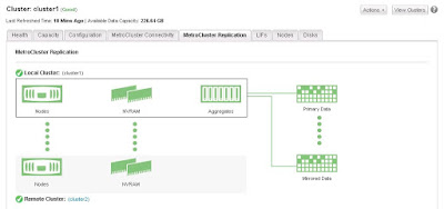
MetroCluster Replication Status
In case of any failure, status changed as below
Also we can check the status of MetroCluster from the Ontap console:
metrocluster show
Recommended or Supported FAS controllers, Disk shelves and FC switch:
Although zero downtime is assured there are very few demerits in MetroCluster and the beauty of NetApp is they actually admit these
è
Zero Data Loss
è
Set it once simplicity
è
Automatic Replication
è
Seamless integration
è
Supports both SAN & NAS
è
Ability to perform Maintenance
è
Ability to perform tech refresh
è
Metro Cluster enables the maintenance beyond DC
Types of MetroCluster
Stretched
MetroCluster: - Where the DR site can be of not more than 500meters (No
switches or bridges are required by default as the connection will be direct
using optical cable)
Two-node setup
without ATTO bridges and only with optical cable
è
Bridges or switches not required
è
Supports optical connectivity
è
Virtual interface over Fibre Channel (FC-VI) is
cabled directly
è
Connections are direct across sites using patch
panels to disk shelves with optical SAS
Two-node setup with
SAS bridges
è
FC-VI is
cabled directly
è
Maximum
distance is 500m with 2Gbps or 150m with 8Gbps
Fabric-attached
MetroCluster: - Which can be extended up to 200Kms
Some Key Points to
note:
The root aggregate requires two or three disks
Need to have minimum of two shelves per site
Disk assignment must be manual even in the event of disk
failure as well
ISL and redundant fabrics connect the two clusters and their
storage
All Storage is fabric attached and visible to all nodes
Now we need to
understand how data is secured attaining zero downtime with MetroCluster
èMetro cluster uses Syncmirror technology to
perform continuous data synchronisation across the DR site with aggregate
mirroring
è
Writes are mirrored synchronously to both plexes
and by default Read operation happens
From local plex
è
A special hidden volume that contains metadata
is located in the data aggregate of each
Node or in a single aggregate in a cluster
holds all the meta data.
Note:- All Aggregates are mirrored with the copies at DR
site including root aggregate
To dig in more: How
the whole site data replicated to DR
In aggregate mirroring, a mirrored aggregate is one WAFL (
Write Anywhere File Layout ) storage file system with two physically separated and
synchronously updated copies on disks or array LUNs. The copies are called
Plexes.
Data ontap always names the first plex as plex0 and second
plex1. Each flex is a physical copy of the same WAFL file system and consists
of one or more RAID groups.
As we know syncmirror can be used only at aggregate level (
Including all flexvol in the aggregate ) but not flexvol, each aggregate will
have two synchronously mirrored plexes, the local plex, plex0 and the remote
plex, plex1. Data is written to the local plex, plex0 and then synchronously
replicated to remote plex, plex1 over the ISL. Reads are always from the plex0.
As we see above Securing data is ok but how
about configuration is secured
Here comes the NVRAM in to picture, NVRAM on each node is
split in to four partitions to make the full use of NVRAM memory.
Note:- Each Node
mirror its NVRAM to two other node: its HA partner and its DR partner
In normal operation, three of the four NVRAM partitions are
used
Partition 1: For the
node self
Partition 2: For HA partner
Partition 3: For DR partner
And partition 4 would manage additional node in the event of
takeover and switchover.
The overhead of the NVRAM split is managed by System Performance
Modeler (SPM) tool, which is not affected
when compared to 7-Mode
Configuration replication service (CRS) replicates the configuration
of each cluster to another.
By default a volume of 10GB size is created on each node to
hold the replicated cluster data. Which acts as meta data volume.
Ex:- A change on Cluster A is logged in to the cluster A
metadata volume and then CRS replicates the change to cluster B
MetroCluster Replication Mechanism
è
NVRAM is mirrored to the HA partner and to the
DR partner
è
Disk traffic is mirrored at the aggregate level
è
Cluster configuration is replicated over a
peered network, Which means this doesn’t need a dedicated network
Reviewing the Failure Events:
Failure Events
|
7-Mode
|
2-Node DR group
|
4-Node DR group
|
One disk or two disk Failure
|
Data is still available
|
Data is still available
|
Data is still available
|
More than two disk failure
|
The serving plex serves data; the node is unaffected
|
The serving plex serves data; the node is unaffected
|
The serving plex serves data; the node is unaffected
|
Shelf failure
|
The surviving plex serves data
|
The surviving plex serves data
|
The surviving plex serves data
|
Switch failure
|
Data is served via the other path
|
Data is served via the other path
|
Data is served via the other path
|
Switch ISL failure
|
Data is available from the local node if the ISLs are down, DR
protection is offline
|
Data is available from the local node if the ISLs are down, DR
protection is offline
|
Data is available from the local node if the ISLs are down, DR
protection is offline
|
Node Failure ( Panic, Power-off, and so on)
|
Automatic failover occurs to the remote node
|
Automatic failover occurs to the remote node
|
Automatic failover occurs to the remote node
|
Peered clusted link failure
|
n/a
|
Data remains available from the local cluster, cluster config changes
are not replicated affecting DR
|
Data remains available from the local cluster, cluster config changes
are not replicated affecting DR
|
Failure of both nodes in an HA group
|
All data offline
|
All data offline
|
Automatic switchover (SO) with tie-breaker occurs
|
How a failure is detected ? What would be the plan of action after a failure of site ?
When there is complete site failure the surviving storage controller cannot distinguish between site failure or just a network partition. Here come the tie breaker in to picture which needs to be deployed in a separate data center which helps the surviving controller to decide what to do next.
Note: If the third data center is not available and Tie-Breaker cannot be implemented the storage controller takes no action and the storage administrator needs to do manual forced takeover of the storage resources on the surviving controller. ( Imagine you have only a production and DR site and don't have a third site), scratching your head where to deploy TIE-BREAKER setup a server in your office and install REDHAT (Tie breaker runs on Redhat Linux ) which will monitor your both sites or data center and instruct your MetroCluster what to do in the event of a failure.
Here are the mediums to monitor MetroCluster
Tie Breaker: After installing tie breaker on Redhat Linux, use the command
netapp-metrocluster-tiebreaker-software-cli to use the metrocluster monitoring commands
Check the status of the MetroCluster
monitor show -stats ( Shows when was the last cluster unreachable time, last intersite connectivity down time )
Another way to monitor the MetroCluster is from OCUM (Oncommand Unified Manager)
MetroCluster connectivity showing all healthy
MetroCluster Replication Status
In case of any failure, status changed as below
Also we can check the status of MetroCluster from the Ontap console:
metrocluster show
Recommended or Supported FAS controllers, Disk shelves and FC switch:
Controllers(
Including Flex Arrays)
|
Disk
Shelves
|
Switches
|
FAS 3220, 3250
FAS 6210, 6240, 6280, 6220, 6250, 6290
FAS 8020, 8040, 8060, 8080 EX
|
DS 4243
DS 2246
DS 4246
|
Brocade 6505
Brocade 6510
Cisco 9148
|
è Switchover is disruptive for SMB protocol, where continuous available shares will have less than 60Seconds outage
è Doesn’t support infinite volume
è SSD partitioning in Flash Pool
è Advance Disk Partitioning (ADP)
è NetApp Storage Encryption (NSE)


