Cluster Mode Introduction :-
Virtualization plays a key role in clustered Data Ontap
Before server virtualization, system administrators frequently deployed applications on dedicated servers in order to maximize application performance, and to avoid the instabilities often encountered when combining multiple applications on the same operating system instance. While this design approach was effective, it also had the following drawbacks:
• It did not scale well — adding new servers for every new application was expensive.
• It was inefficient — most servers are significantly under-utilized, and businesses are not extracting the full benefit of their hardware investment.
• It was inflexible — re-allocating standalone server resources for other purposes is time consuming, staff intensive, and highly disruptive.
Server virtualization directly addresses all three of these limitations by decoupling the application instance from the underlying physical hardware.
Multiple virtual servers can share a pool of physical hardware, allowing businesses to consolidate their server workloads to a smaller set of more effectively utilized physical servers.
Additionally, the ability to transparently migrate running virtual machines across a pool of physical servers reduces the impact of downtime due to scheduled maintenance activities.
Clustered Data ONTAP brings these same benefits, and many others, to storage systems. As with server virtualization, clustered Data ONTAP enables you to combine multiple physical storage controllers into a single logical cluster that can non-disruptively service multiple storage workload needs. With clustered Data ONTAP you can:
• Combine different types and models of NetApp storage controllers (known as nodes) into a shared
physical storage resource pool (referred to as a cluster).
• Support multiple data access protocols (CIFS, NFS, Fibre Channel, iSCSI, FCoE) concurrently on the same storage cluster.
• Consolidate various storage workloads to the cluster. Each workload can be assigned its own Storage Virtual Machine (SVM), which is essentially a dedicated virtual storage controller, and its own data volumes, LUNs, CIFS shares, and NFS exports.
• Support multi-tenancy with delegated administration of SVMs. Tenants can be different companies,
business units, or even individual application owners, each with their own distinct administrators whose admin rights are limited to just the assigned SVM.
• Use Quality of Service (QoS) capabilities to manage resource utilization between storage workloads.
• Non-disruptively migrate live data volumes and client connections from one cluster node to another.
• Non-disruptively scale the cluster out by adding nodes. Nodes can likewise be non-disruptively removed from the cluster, meaning that you can non-disruptively scale a cluster up and down during hardware refresh cycles.
• Leverage multiple nodes in the cluster to simultaneously service a given SVM's storage workloads.
• This means that businesses can scale out their SVMs beyond the bounds of a single physical node in
response to growing storage and performance requirements, all non-disruptively.
• Apply software and firmware updates, and configuration changes without downtime
Cluster Networking:-
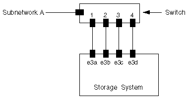
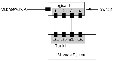
Ports are the physical Ethernet and Fibre Channel connections on each node, the interface groups (ifgrps) you can create to aggregate those connections, and the VLANs you can use to subdivide them.
A logical interface (LIF) is essentially an IP address that is associated with a port, and has a number of associated characteristics such as an assigned home node, an assigned physical home port, a list of physical ports it can fail over to, an assigned SVM, a role, a routing group, and so on.
A given LIF can only be assigned to a single SVM, and since LIFs are mapped to physical network ports on cluster nodes this means that an SVM runs, in part, on all nodes that are hosting its LIFs.
Routing tables in clustered Data ONTAP are defined for each Storage Virtual Machine. Since each SVM has it’s own routing table, changes to one SVM’s routing table does not have impact on any other SVM’s routing table.
IPspaces are new in Data ONTAP 8.3, and allow you to configure a Data ONTAP cluster to logically separate one IP network from another, even if those two networks are using the same IP address range.
IPspaces are a mult-tenancy feature that allow storage service providers to share a cluster between different companies while still separating storage traffic for privacy and security.
Every cluster includes a default IPspace to which Data ONTAP automatically assigns new SVMs, and that default IPspace is probably sufficient for most NetApp customers who deploy a cluster within a single company or organization that uses a non-conflicting IP address range.
Broadcast Domains are also new in Data ONTAP 8.3, and are collections of ports that all have access to the same layer 2 networks, both physical and virtual (i.e., VLANs).
Every IPspace has it’s own set of Broadcast Domains, and Data ONTAP provides a default broadcast domain to go along with the default IPspace. Broadcast domains are used by Data ONTAP to determine what ports an SVM can use for it’s LIFs.
Subnets in Data ONTAP 8.3 are a convenience feature intended to make LIF creation and management easier for Data ONTAP administrators.
A subnet is a pool of IP addresses that you can specify by name when creating a LIF. Data ONTAP will automatically assign an available IP address from the pool to the LIF, along with a subnet mask and a gateway.
A subnet is scoped to a specific broadcast domain, so all the subnet’s addresses belong to the same layer 3 network. Data ONTAP manages the pool automatically as you create or delete LIFs, and if you manually configure a LIF with an address from the pool, it will detect that the address is in use and mark it as such in the pool.
DNS Zones allow an SVM to manage DNS name resolution for it’s own LIFs, and since multiple LIFs can share the same DNS name, this allows the SVM to load balance traffic by IP address across the LIFs. To use DNS Zones you must configure your DNS server to delegate DNS authority for the subdomain to the SVM.
Virtualization plays a key role in clustered Data Ontap
Before server virtualization, system administrators frequently deployed applications on dedicated servers in order to maximize application performance, and to avoid the instabilities often encountered when combining multiple applications on the same operating system instance. While this design approach was effective, it also had the following drawbacks:
• It did not scale well — adding new servers for every new application was expensive.
• It was inefficient — most servers are significantly under-utilized, and businesses are not extracting the full benefit of their hardware investment.
• It was inflexible — re-allocating standalone server resources for other purposes is time consuming, staff intensive, and highly disruptive.
Server virtualization directly addresses all three of these limitations by decoupling the application instance from the underlying physical hardware.
Multiple virtual servers can share a pool of physical hardware, allowing businesses to consolidate their server workloads to a smaller set of more effectively utilized physical servers.
Additionally, the ability to transparently migrate running virtual machines across a pool of physical servers reduces the impact of downtime due to scheduled maintenance activities.
Clustered Data ONTAP brings these same benefits, and many others, to storage systems. As with server virtualization, clustered Data ONTAP enables you to combine multiple physical storage controllers into a single logical cluster that can non-disruptively service multiple storage workload needs. With clustered Data ONTAP you can:
• Combine different types and models of NetApp storage controllers (known as nodes) into a shared
physical storage resource pool (referred to as a cluster).
• Support multiple data access protocols (CIFS, NFS, Fibre Channel, iSCSI, FCoE) concurrently on the same storage cluster.
• Consolidate various storage workloads to the cluster. Each workload can be assigned its own Storage Virtual Machine (SVM), which is essentially a dedicated virtual storage controller, and its own data volumes, LUNs, CIFS shares, and NFS exports.
• Support multi-tenancy with delegated administration of SVMs. Tenants can be different companies,
business units, or even individual application owners, each with their own distinct administrators whose admin rights are limited to just the assigned SVM.
• Use Quality of Service (QoS) capabilities to manage resource utilization between storage workloads.
• Non-disruptively migrate live data volumes and client connections from one cluster node to another.
• Non-disruptively scale the cluster out by adding nodes. Nodes can likewise be non-disruptively removed from the cluster, meaning that you can non-disruptively scale a cluster up and down during hardware refresh cycles.
• Leverage multiple nodes in the cluster to simultaneously service a given SVM's storage workloads.
• This means that businesses can scale out their SVMs beyond the bounds of a single physical node in
response to growing storage and performance requirements, all non-disruptively.
• Apply software and firmware updates, and configuration changes without downtime
Cluster Networking:-
Ports are the physical Ethernet and Fibre Channel connections on each node, the interface groups (ifgrps) you can create to aggregate those connections, and the VLANs you can use to subdivide them.
A logical interface (LIF) is essentially an IP address that is associated with a port, and has a number of associated characteristics such as an assigned home node, an assigned physical home port, a list of physical ports it can fail over to, an assigned SVM, a role, a routing group, and so on.
A given LIF can only be assigned to a single SVM, and since LIFs are mapped to physical network ports on cluster nodes this means that an SVM runs, in part, on all nodes that are hosting its LIFs.
Routing tables in clustered Data ONTAP are defined for each Storage Virtual Machine. Since each SVM has it’s own routing table, changes to one SVM’s routing table does not have impact on any other SVM’s routing table.
IPspaces are new in Data ONTAP 8.3, and allow you to configure a Data ONTAP cluster to logically separate one IP network from another, even if those two networks are using the same IP address range.
IPspaces are a mult-tenancy feature that allow storage service providers to share a cluster between different companies while still separating storage traffic for privacy and security.
Every cluster includes a default IPspace to which Data ONTAP automatically assigns new SVMs, and that default IPspace is probably sufficient for most NetApp customers who deploy a cluster within a single company or organization that uses a non-conflicting IP address range.
Broadcast Domains are also new in Data ONTAP 8.3, and are collections of ports that all have access to the same layer 2 networks, both physical and virtual (i.e., VLANs).
Every IPspace has it’s own set of Broadcast Domains, and Data ONTAP provides a default broadcast domain to go along with the default IPspace. Broadcast domains are used by Data ONTAP to determine what ports an SVM can use for it’s LIFs.
Subnets in Data ONTAP 8.3 are a convenience feature intended to make LIF creation and management easier for Data ONTAP administrators.
A subnet is a pool of IP addresses that you can specify by name when creating a LIF. Data ONTAP will automatically assign an available IP address from the pool to the LIF, along with a subnet mask and a gateway.
A subnet is scoped to a specific broadcast domain, so all the subnet’s addresses belong to the same layer 3 network. Data ONTAP manages the pool automatically as you create or delete LIFs, and if you manually configure a LIF with an address from the pool, it will detect that the address is in use and mark it as such in the pool.
DNS Zones allow an SVM to manage DNS name resolution for it’s own LIFs, and since multiple LIFs can share the same DNS name, this allows the SVM to load balance traffic by IP address across the LIFs. To use DNS Zones you must configure your DNS server to delegate DNS authority for the subdomain to the SVM.